Thermal balance and thermal vacuum tests often require manual coordination between operators running the thermal control system and those managing the EGSE. This fragmented test control creates a persistent challenge for AIT engineers, leading to delays, miscommunication, and inconsistent response times during critical phases of the test.
Integrating STAMP thermal testing software with spacecraft Electrical Ground Support Equipment (EGSE) addresses this coordination challenge by creating direct data and command pathways between systems. The automated integration helps maintain schedule discipline and traceability while reducing manual coordination requirements.
In the article we will show how a direct connection between STAMP and EGSE results in an improved test performance. Another point of consideration for this direct data exchange is that STAMP is complementary to EGSE systems, and particularly CCSs.
 Figure 1: Thermal test setup. This illustration displays the situation, where STAMP and EGSE systems work independently from each other. STAMP monitors and controls all devices outside the spacecraft, the EGSE systems monitor and control the devices within the spacecraft. In this case, operators handle the interaction between both systems, although a direct data exchange would be the preferred setup.
STAMP thermal testing software connects to EGSE systems through standardized communication protocols, eliminating manual data transfer between thermal analysis and spacecraft checkout operations. This connection enables real-time thermal parameter monitoring during spacecraft system tests.
The integration typically employs TCP/IP socket connections, allowing STAMP to receive telemetry data directly from spacecraft subsystems while simultaneously feeding thermal model predictions back to the EGSE control systems. Test engineers configure data mapping tables that define which thermal sensors correspond to specific spacecraft components under evaluation.
STAMP Import/Export Implementation Details
There are several data sharing mechanisms in STAMP that allow for the export and import of both real-time and historical data. Here, we describe the two principal interfaces that can be used for the EGSE data sharing: the Socket interface and system specific import applications.
Socket Interface
To interact with the EGSE or any other software package, a socket interface is provided. STAMP communicates through a simple, well documented, ASCII based, communication protocol, which does not require any external libraries to be linked. The data is imported in TSV format, which should contain a unique sensor name, time stamp and a value. This protocol has been successfully used by numerous missions to share data between STAMP and the
Central Checkout Systems developed by Terma, as well as other systems.
Data Export
Data can be exported within the local network, or using the Remote Client, in a remote environment. Remote Client. This exported data can be either real-time data or a block of data for a certain time-period.
Data Import
STAMP considers imported data to be similar to an acquisition device, as it acquires data from another software package. A data import from any EGSE system to STAMP is therefore configured in the exact same way as a scanner that is connected through a TCP socket interface. See Figure 2. To increase security, STAMP will only allow incoming connections from the IP addresses and ports specified in the interface. Imported data will be shown as real sensors together with the acquired data by STAMP. See Figure 4. By treating imported data as normal sensors, STAMP allows the user to place alarms on these imported sensor values and present them in the exact same way as regular STAMP data.
Interface Application
In addition to the socket connection, STAMP can also acquire data from, and present data to systems that are equipped with an OPC DA or UA server.
Benefits of Automated Data Exchange Between STAMP and EGSE
 Figure 2: A screenshot of the STAMP data import configuration window.
Direct data exchange between STAMP and EGSE software will result in the following benefits:
Improved Hardware Interfacing
During a test, EGSE systems need to communicate with facility equipment, such as sensors or power supplies. Every change of facility equipment requested during the thermal test involves interaction between the spacecraft test operators and the facility operators. This is acceptable when the frequency of parameter changes is low, but for higher-frequency operations, a direct data link would be preferable. For example, some payloads might still be missing during testing of the qualification model of the spacecraft. To compensate for the energy that is produced by the missing payload devices, heaters are used. These heaters, powered by power supplies (PSUs), are set to dissipate the same amount of thermal energy as the device. STAMP controls the power supply as part of the facility equipment. Now, every time the payload device (simulated by the heater) is switched on or off, the spacecraft test operator must submit a paper request form to the facility operator with a new setpoint for the power supply controlling the heater. The facility operator will process this request in STAMP, where STAMP logs, verifies, and implements the setpoints on the controlled power supplies.
A direct data link allows the EGSE to present setpoints directly to STAMP, which directly improves the performance of the test. There is no lost time when updating setpoints; the software directly controls the PSU (through STAMP). Traceability and verification of setpoints remain in place. These are and will still be handled by STAMP downstream from setpoint injection.
Besides the improved performance, also the reliability of the test will increase: There is no chance of STAMP misreading or misunderstanding a request. The
spacecraft testing team doesn’t have to spend time on setpoint change requests and will therefore be able to better focus on the test.
Finally, using STAMP to control the facility, EGSE systems don’t have to invest in the development of hardware drivers, as they are already incorporated into STAMP. The only adjustment is the implementation of the communication protocol for STAMP, which is a simple and straightforward TCP connection.
Presentation of Merged Data
As discussed before, STAMP handles the thermal analysis of the facility and does the read-out from the thermal sensors that are placed on the outside of the spacecraft. Thermal data measured inside the spacecraft are sent through house-keeping telemetry to the EGSE systems. The only way to obtain a complete picture of the thermal behaviour of the spacecraft is to map these thermal test sensors to the thermal flight sensors. It takes time to check the analysis of data from different systems by hand and can easily lead to errors or mistakes. Using the automated data sharing between the EGSE system and STAMP, thermal test results can be merged much faster, even in real-time. Without any loss of precision, test results can be analysed and visualized. The thermal data can be shown from inside the spacecraft in STAMP presentations, just like the 3D synoptic presentations as shown in Figure 3.
Besides thermal data exchange, the EGSE will also be able to import test information into the STAMP logbook, such as which test step is run at what time. Logbook entries can be made visible in the graphs and other presentations, as shown in Figure 4. In this way a complete picture with the highest possible accuracy can be achieved.
 Figure 3: Sensor placement on a spacecraft in a Vacuum chamber. This illustration displays the placement of sensors on the spacecraft, as visualized in STAMP’s 3D virtual reality display3. The colored balls indicate the sensors placed on the spacecraft with a color scale indicating the current temperature
.
 Figure 4: Example of merged data from EGSE and STAMP. The STAMP sensors represent sensors that are located on the outside of the spacecraft. The EGSE sensor represents thermal data from inside the spacecraft, which is extracted from the house-keeping data packets. The EGSE has exported the data together with test information to STAMP. STAMP merges the facility data with the test sensor data and displays all information on the screen. Note that the graph shows simulated data.
Availability of Remote Real-Time Data Access
Using a direct data exchange between EGSE systems and STAMP, facility customers will benefit from the utilities provided both by STAMP and EGSE. Here, we focus on the Remote Client, a tool in STAMP that allows teams from distant locations to participate fully in the thermal test through a secure connection. The Remote Client allows real-time and offline monitoring and analysis of spacecraft and facility test results. When EGSE data are imported into STAMP, facility customers working off-site can use the Remote Client to follow the test as if they were present on-site. Furthermore, the Remote Client allows for real-time exporting of data to other systems. Here the test data can be processed in real-time at the customer site using the usual in-house tools. If needed, the results can be shown and discussed quickly with in-house experts, even while the test is still running. Any possible problem can therefore quickly be identified. This process will reduce the cost of a thermal test and will increase efficiency in the case of problems.
Offline and Real-Time Test Monitoring
The Remote Client is given to the facility customer. Here the client makes a connection to the test server, where the selected test database is downloaded into a local database. As long as the connection remains, the client receives real-time test data updates. The local copy of the test database also allows the facility customer to work offline during and after the thermal test. On reconnection to the test database, the local copy will be brought up to date, so the facility customer has access to the latest possible data.
Security Aspects
 Figure 5: Setup of the remote access of test data.
Sending real-time data online requires strong security. STAMP uses a range of techniques to address this concern. The main components are shown in Figure 5. The production server stores all test configuration and data in the test database. The firewall 1 blocks all incoming connections and allows only external connections that are created from inside the test centre to the outside. An intermediate server, the so-called “replication server”, is set up in the Demilitarized Zone (DMZ). It contains a copy of the test configuration and test data. The replication server distributes the data to connected Remote Clients and is protected by a second firewall. Firewall 2 only allows incoming connections from Remote Clients, if the client can present a trusted and valid client certificate that is signed by the test centre. Secure usernames and passwords define what sensors, PSUs and synoptics a client can view. All data are sent with a strong encryption, which makes it practically impossible to intercept or alter the data during its exchange. Instead of handling security internally, STAMP acts as a CGI-bin application that is approached through a webserver. The security parameters are configured on this web server, allowing IT departments to configure it with the level of security they desire.
Unified Test Environment
STAMP integration with spacecraft checkout systems is an improvement in thermal test automation. It reduces human error, maintains tighter schedules, and improves cross-system traceability. The integration of STAMP thermal testing software with spacecraft EGSE systems creates a safe and efficient test environment, and it secures reliable operations during critical spacecraft checkout.
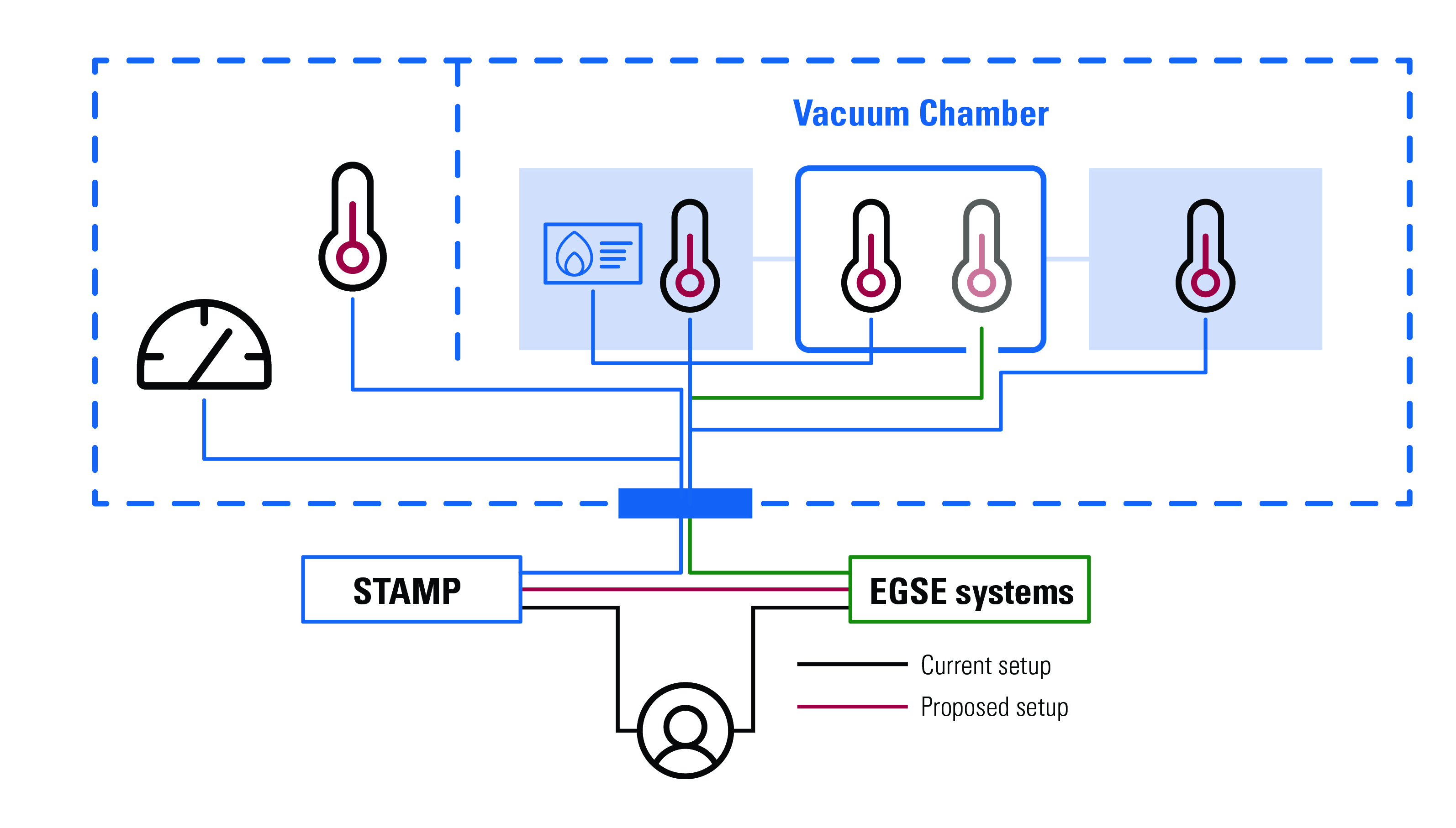 Figure 1: Thermal test setup. This illustration displays the situation, where STAMP and EGSE systems work independently from each other. STAMP monitors and controls all devices outside the spacecraft, the EGSE systems monitor and control the devices within the spacecraft. In this case, operators handle the interaction between both systems, although a direct data exchange would be the preferred setup.
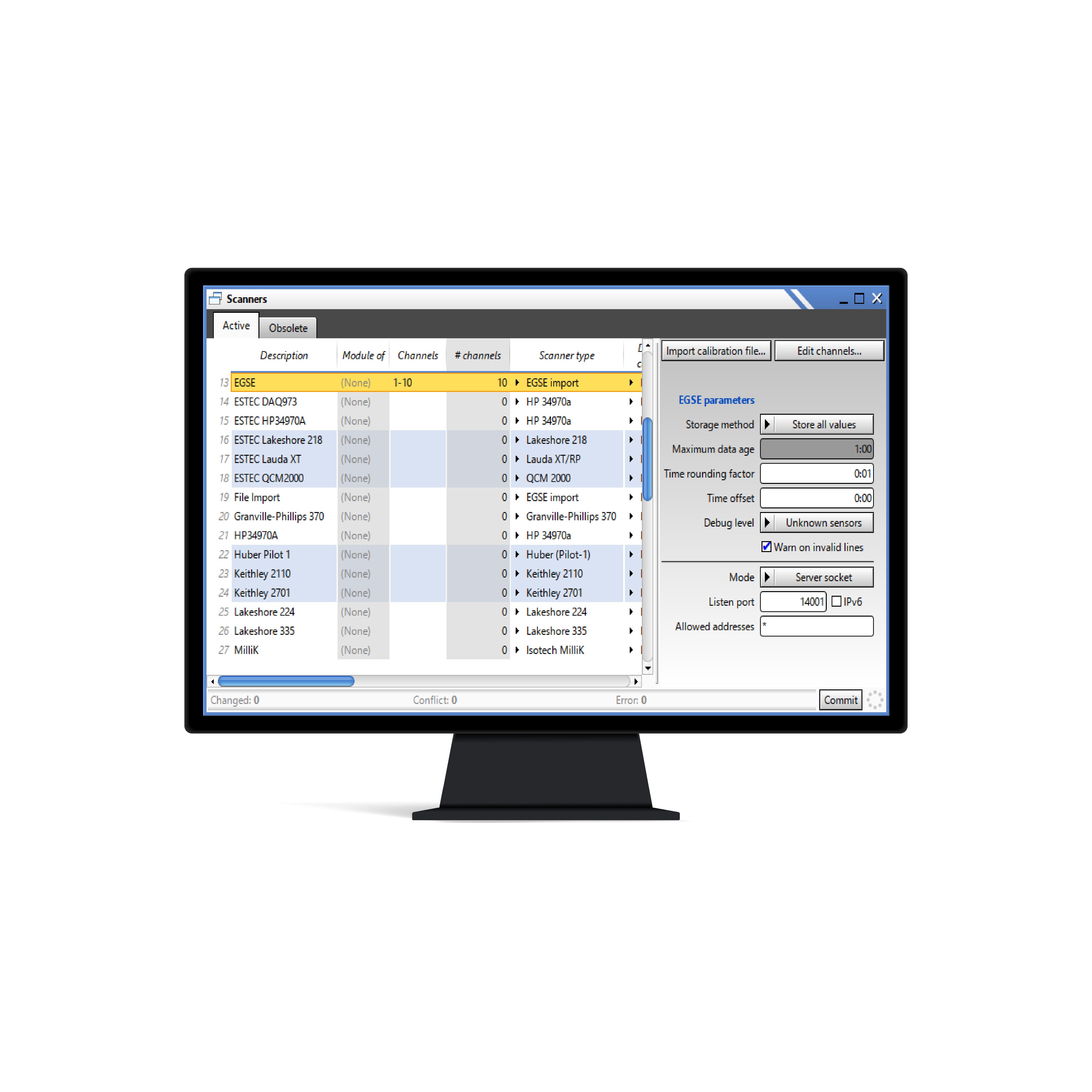 Figure 2: A screenshot of the STAMP data import configuration window.
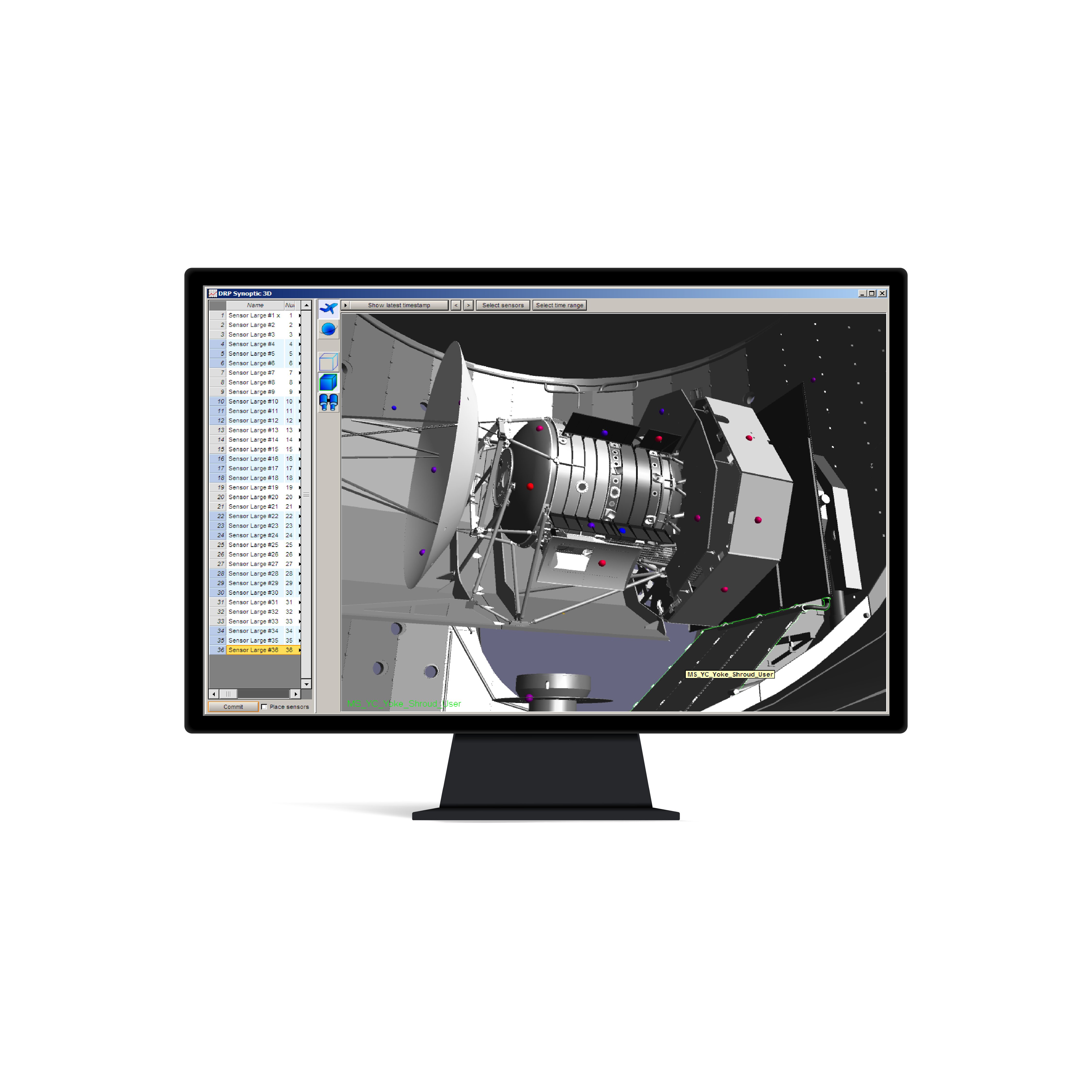 Figure 3: Sensor placement on a spacecraft in a Vacuum chamber. This illustration displays the placement of sensors on the spacecraft, as visualized in STAMP’s 3D virtual reality display3. The colored balls indicate the sensors placed on the spacecraft with a color scale indicating the current temperature.
 Figure 4: Example of merged data from EGSE and STAMP. The STAMP sensors represent sensors that are located on the outside of the spacecraft. The EGSE sensor represents thermal data from inside the spacecraft, which is extracted from the house-keeping data packets. The EGSE has exported the data together with test information to STAMP. STAMP merges the facility data with the test sensor data and displays all information on the screen. Note that the graph shows simulated data.
 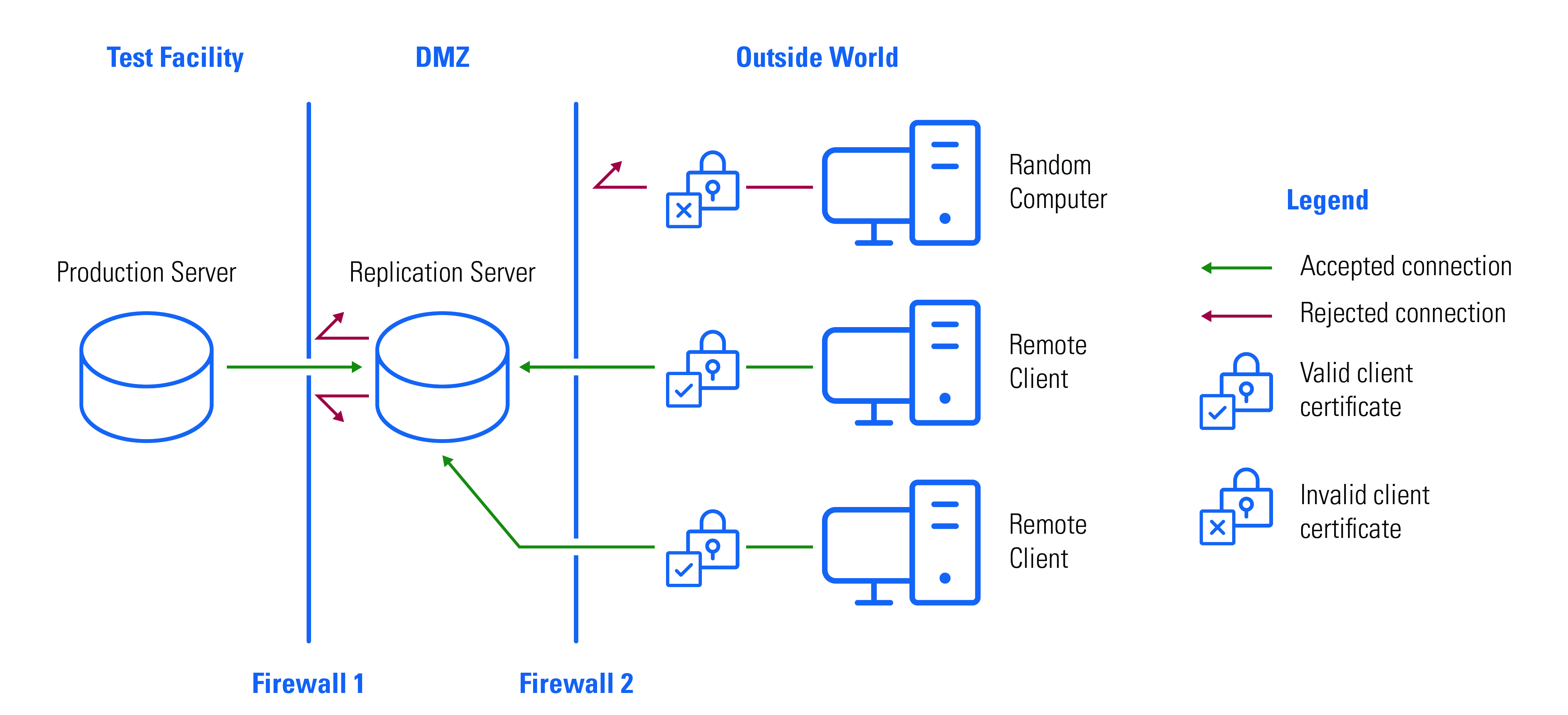 Figure 5: Setup of the remote access of test data.